Page 10 - 2018村田型錄1-46
P. 10

R R
          滾柱減速機構成


          STRUCTURE OF ROLLER REDUCER
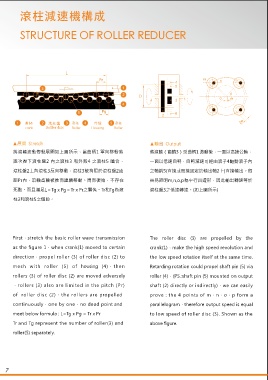


                                                                                                                                                                                                            4  Internal rollers
                                                                                                                                                                                                                         1 外滾柱
                              L                                                                                                                                                                                             External rollers
                                             Pr                                                                                                                                                                              2  Needle pin

                                                                                                                                                                                          D1 針齒直徑  Needle pin pitch diameter  Needle pin(Pin gear)diameter  5 (Pinroll)


            曲柄        滾柱盤                  外殼                                                                                                                                                                            3        Shaft pin
                crank                Roller disc          Roller              Housing             Roller                                                                                                                    Roller disc


        ▲展開  Stretch                                                ▲輸出  Output                                                  ▲激波                                                       ▲組合  Assembly
       將滾輪波動傳動展開如上圖所示,當曲柄1 單向移動將                                    將滾輪(齒輪3)受曲柄1 激動後,一面以高速公轉,                                    當外殼4的齒廓採用圓形滾柱5和激波器選用標準                                    以上機構精巧組合如上圖所示,當滾柱盤3上之內滾

       逐次壓下滾柱盤2 內之滾柱3 和外殼4 之滾柱5 嚙合,                                 一面以低速自轉,自轉減速可經由滾子4驅動滾子內                                      偏心圓時,其激波規律類似曲柄滑塊運動的規律 (如                                  柱4較小時,尤其在傳動比較大狀況下,滾柱內無法
       滾柱盤2上各滾柱3反向移動,滾柱3被拘限於滾柱盤2齒                                   之軸銷5(直接或間接固定於輸出軸2上)直接輸出。很                                    上圖所示)。                                                    安置軸銷 5時,通常將其置放於滾柱盤3上,其輸出

       距Pr內,滾輪齒輪被推而連續移動。周而復始,不存在                                    容易證明m,n,o,p為平行四邊形,因此輸出轉速等於                                                                                             轉速仍然不變,全系統基本上為純滾動接觸,機械
                                                                                                                                  S =Rp Cos β-e Cos ω
       死點。而且滿足L=Tg x Pg=Tr x Pr之關係。Tr和Tg為滾                          滾柱盤3之低速轉速。(如上圖所示)                                                                                                      損失非常微小,故可得極高之傳動效率。
                                                                                                                                               2
                                                                                                                                         2
                                                                                                                                            2
                                                                                                                                  S' =√Rp -e  Sin ωt-e Cos ωt-RO
       柱3和滾柱5之個數。
                                                                                                                                 Rp=偏心圓理論輪廓半徑                  e=偏心距
                                                                                                                                 Ro=激波器基圓半徑                    ω=偏心圓角速度
                                                                                                                                  β=連杆和導軌中線間夾角                  t=時間參數


       First,stretch the basic roller wave transmission             The  roller  disc  (3)  are  propelled  by  the                                                                        The detail shown as the above figure, when

       as the figure 1,when crank(1) moved to certain               crank(1),make the high speed revolution and                                                                            internal rollers(4) of roller disc (3) are small
       direction,propel roller (3) of roller disc (2) to            the low speed rotation itself at the same time.                                                                        so that shaft pin(5) can’t be inserted into

       mesh  with  roller  (5)  of  housing  (4),then               Retarding rotation could propel shaft pin (5) via                                                                      internal   rollers,especially   high    ratio

       rollers (3) of roller disc (2) are moved adversely           roller (4),(PS.:shaft pin (5) mounted on output                                                                        status, shaft  pin(5)  is  used  to  being  put  in
       ,rollers (3) also are limited in the pitch (Pr)              shaft (2) directly or indirectly),we can easily                                                                        roller disc (3) directly,also maintain the same

       of  roller disc (2),the rollers are propelled                prove : the 4 points of m,n,o,p form a                                                                                 output  speed. Basically,this  system  is
       continuously,one by one,no dead point and                    parallelogram,therefore output speed is equal                                                                          rolling  contact completely  with  very  low

       meet below formula : L=Tg x Pg = Tr x Pr                     to low speed of roller disc (3). Shown as the                                                                          mechanical  loss  and     obtain  very  high

       Tr and Tg represent the number of roller(3) and              above figure.                                                                                                          efficiency.
       roller(5) separately.


   7                                                                                                                                                                                                                                      8
   5   6   7   8   9   10   11   12   13   14   15